
Electrics
Historical
|
The full story of the earlier electrics can be found on the original website, but essentially, it was going to be a traditional track-fed 12v system until the twin-point and crossover unit was constructed (welded-up). The problem was that I couldn't incorporate the track breaks properly or come up with a simple way to switch all of the required circuits/sections.
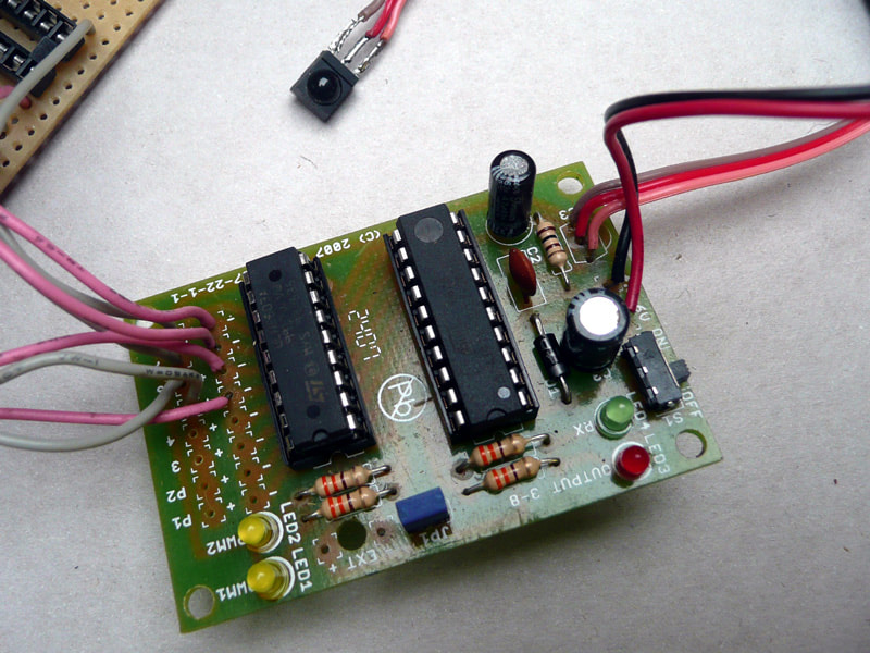
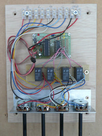
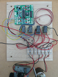
After a depressing lack of progress, I came across an infrared control kit sold by Maplins and decided to switch to battery powered locos. They were made by MUTR, essentially a schools training resources supplier. The units had 2 analogue channels for motor control and 6 digital (on/off) channels (as latching push button switches). After some thought, it was determined that multiple units would allow for running two loco's plus some layout accessories via 5v relays on the on/off circuits. Each loco had a unit and there was one for the layout. |
Ch1 - loco A speed
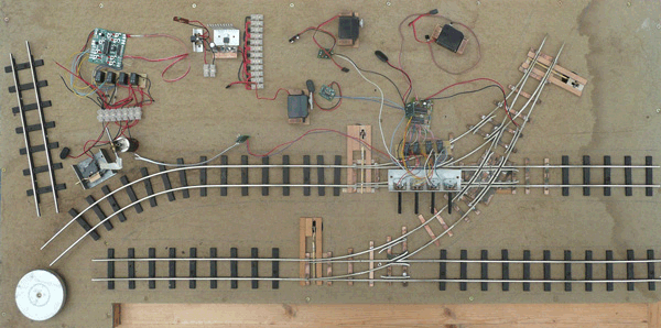
Ch2 - loco B speed Ch3 - loco A fwd/rev Ch4 - loco B fwd/rev Ch5 - point '5' Ch6 - point '6' Ch7 - point '7' Ch8 - this would have to control the turntable on its own! A 9v layout supply was stepped down to 5v and instead of the tiny control unit, it was discovered that a standard Sony TV remote could be used. The layout and locos progressed. Servos were used for point actuators with controllers from MUTR. The turntable was an immense challenge, but another MUTR kit provided the answer. However, the turntable - the main feature on the layout - proved impossible to align and as such the layout fell into disuse. |
Revival
|
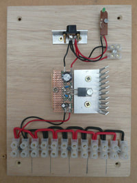
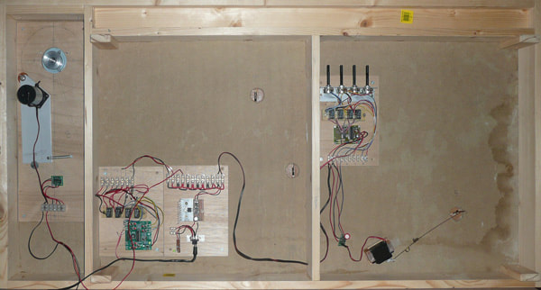
Under lockdown, the layout was retrieved from the shed and reviewed. The turntable was the first thing that had to be addressed. In the intervening years, I'd developed a knowledge of Arduino's and had always wanted to learn how stepper motors worked. I'd been given an Arduino schools pack and now dug out the tiny stepper motor. After many hours of research and numerous YouTube tutorials I knew it was the right solution. Once I'd created a reasonably close semblance of a working program, I purchased a used Nema17 format stepper, which became the turntable drive motor. Both the Arduino and the motor work better on 9v, so an unmodified supply was used from the main board power feed.
|
As loco's would now be R/C rather than IR, channels (buttons) 3 and 4 were free. Their relays were rewired and became the turntable direction activators: 3 = clockwise and 4 = anticlockwise.
For the foreseeable future, the three points will remain being controlled by the IR controller. There is occasional interference causing twitching of the servos, but it is audible rather than actually moving the points and will be investigated. That leaves channel 8 available for something else! |
