Turntable
Historical
|
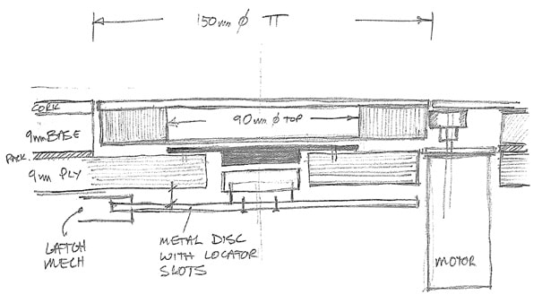
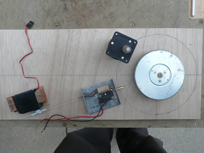
The original turntable was a lovely piece of work. At its core was an old CD turntable - solid and smooth running. Onto it was bolted a plywood disk to take the track. A large geared motor was mounted vertically on a swivelling arm, with a piece of PVC tube on the motor shaft that pressed against the plywood disk to turn the turntable.
The next problem was how to locate the TT track at each road. An aluminium disk was cut and fixed to the turntable. Slots were cut into its edge. A sprung loaded micro-switch was fitted with a cranked blade that was thrust into the disk slots. The turntable was started by a servo retracting the blade clear of the slot, which activated an integral microswitch starting the motor. When a slot was reached, the blade engaged with the slot and disengaged the microswitch and motor power. |
To make the whole unit operable using one on/off switch required another MUTR unit - an IQ3. This was a manually programmable device. Buttons on the unit were pressed in real-time, building up a program. LED's were incorporated such that pressing the 'go' button when an LED was on triggered the table to rotate CW, but pressing when the LED was off triggered a CCW rotation. Pressing again released the blade onto the edge of the plate where it dropped into the next slot and switched the motor off.
It worked beautifully, but aligning the track was near impossible and despite several attempts and modifications, the realisation that I wasn't able to resolve it satisfactorily slowly dawned on me and the layout was consigned to the shed. |
Revival
|
I was determined that in order to resolve the track alignment accuracy problem, the new turntable would have to use a stepper motor drive. For the uninitiated, stepper motors don't just run when power is applied. They require something to control it for every step it makes. The steps are pulses applied via a controller to coils that rotate the shaft through small individual degrees of movement. This makes them ideal for precision movement and are in many household items like printers.
I started with the motor and controller supplied in the Arduino Uno school kit to get the hang of the programming required. I'd used the Uno to operate some doors on Belfield Engineering so another was now required. A smaller Arduino would suffice, so I bought a couple of Nano's, at around £3.25 each. Early forays into stepper motor programming required every step to be hand written, which was laborious, but it worked. I now needed a real motor, which eventually arrived via eBay. A un-specified used motor for under £5, which I now believed to be an Adafruit 324x. It was heavy and spinning the shaft felt wonderful. The Nema17 standard faceplate has four bolt holes ready to receive a mounting plate. |
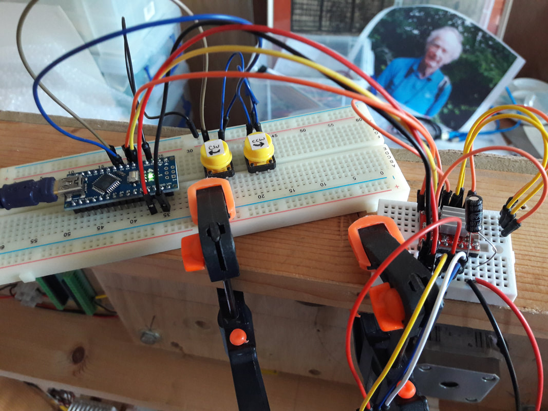
However, there was no controller, but I discovered that suitable controllers were available that took all of the hard slog out of the programming process. For a numpty like me, this still meant hours of research to get to grips with the theory and available models. I plumped for a A4899 controller as the best YouTube video on the subject was using my motor. The size of a postage stamp and costing only a few pounds, it was wonderful when a couple arrived in the post (I manged to 'blow' one of these as well as a Nano!).
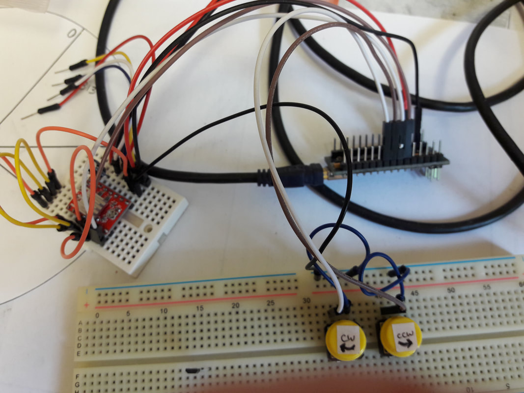
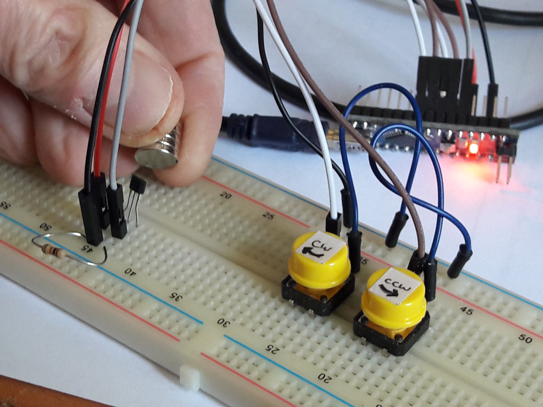
I built up programs slowly, with the components fitted to a breadboard. Just making it rotate was exciting! Then add a couple of buttons and you had awesome control. At this time, I was using the default resolution of the motor, which was 200 steps per revolution = 1.8 degrees. The controller then came into its own. It could be set to half step = 400 steps per revolution, then quarters, eighths and finally sixteenths = 3200 steps per revolution! I was extremely happy, but in order to progress to the next stage of programming, the real turntable had to be completed. |
|
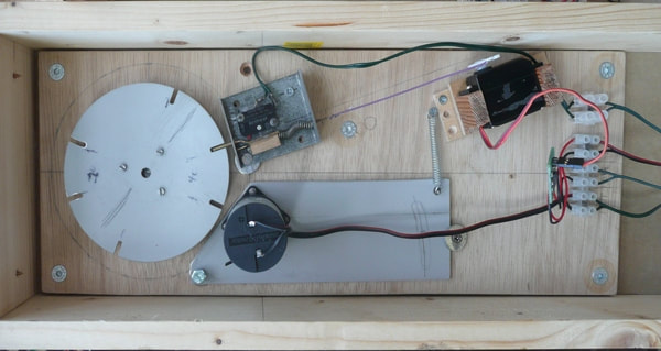
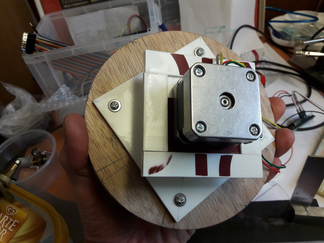
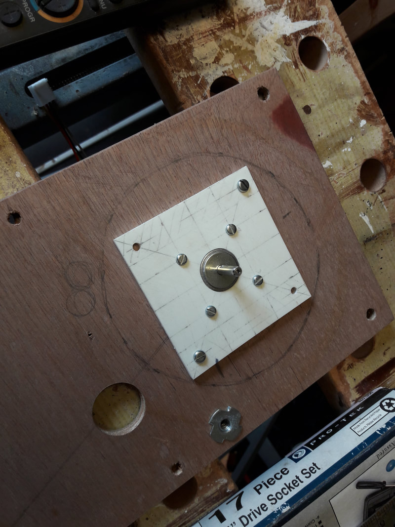
The new turntable needed an adjustable mounting system with two frames - one for the turntable top to spindle and one to fit the motor body onto the baseboard.
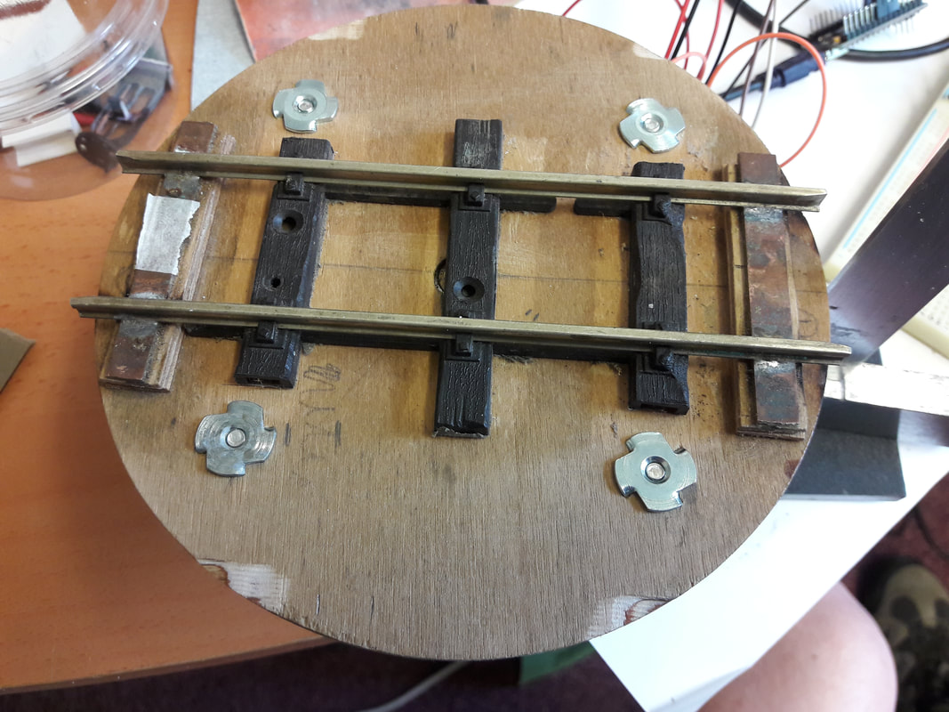
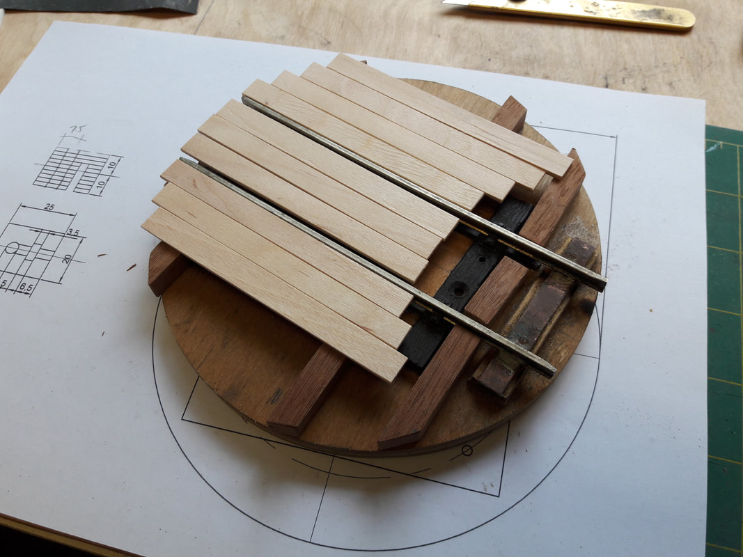
The original turntable was reused. Four M4 bolts would fix it to the plate underneath, that attached to the motor spindle. Note tee-nuts used for fixing bolts on the deck upper surface where the deck planking would be fitted at a later date. |
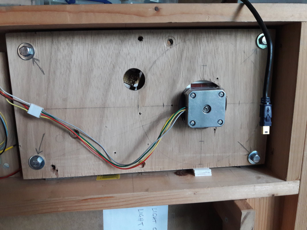
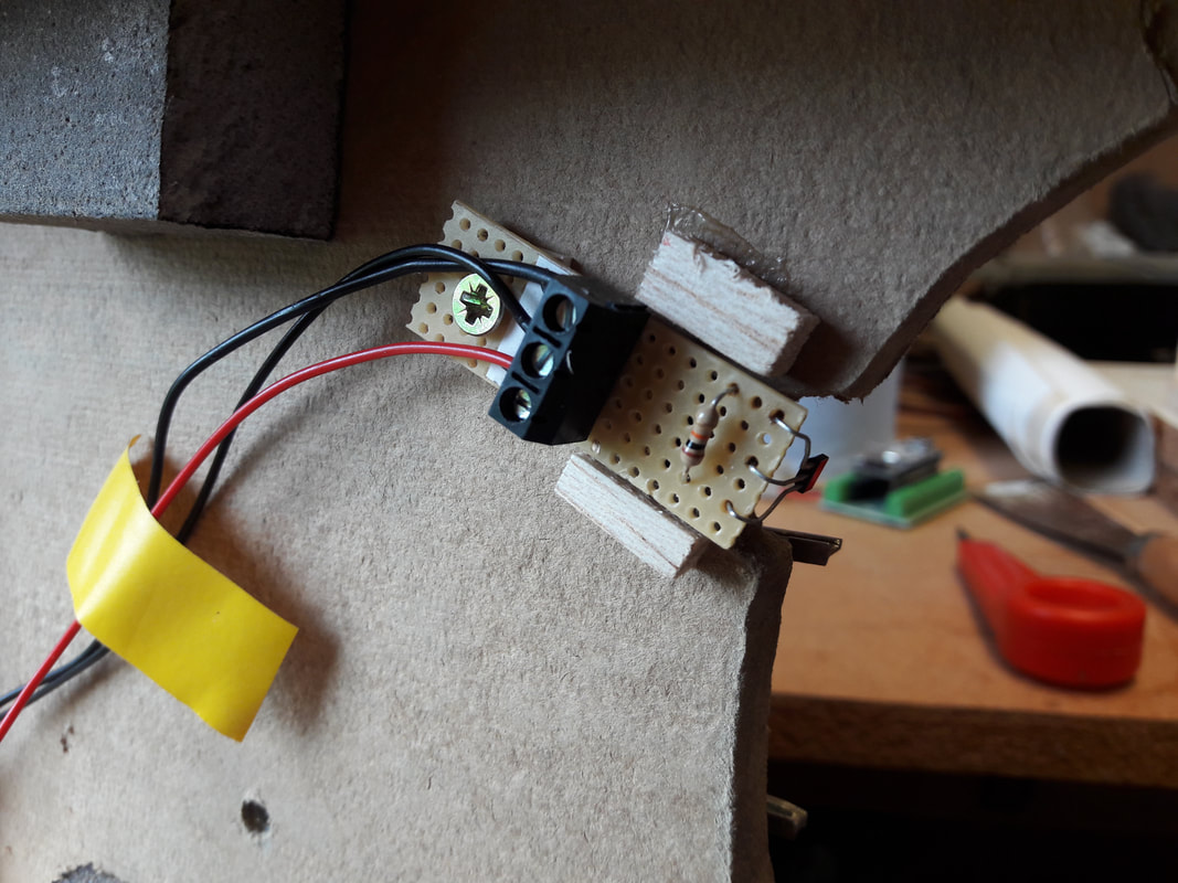
The motor mount was fixed to a plywood base plate (which was part of the original turntable assembly) with four M6 bolt fixings. The bolts go into tee-nuts in the top of the baseboard. A firm sponge panel is sandwiched between main board a motor board pushing against the ply back panel, allowing the bolts to be adjusted from below to get the track alignment and level correct.
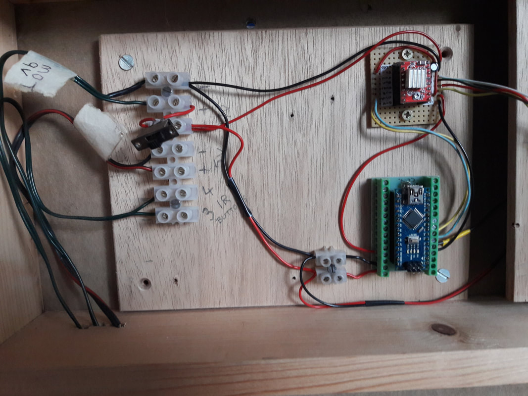
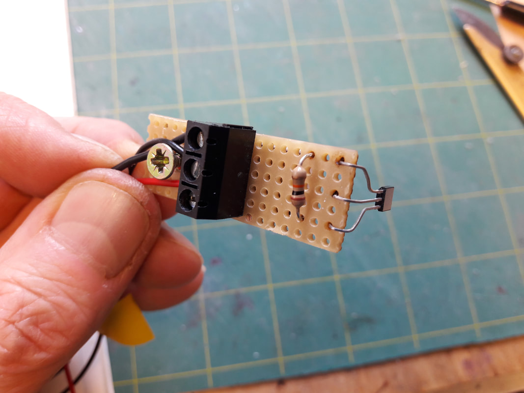
Finally, the Arduino and A4899 controller were mounted on break-out bases to allow screwed wire connections. |
|
There were some irritating teething problems transferring the electronics onto the baseboard, but after exhaustive investigations, a faulty breakout connector was found and the problem resolved. The motor could be controlled to rotate, but next, alignment with the tracks was required. The program had built-in approximate step-counts, which through trial and error were refined to align the rails exactly. However, after powering up, the motor has to know where 'zero' is. To do this, the turntable must locate a fixed position. Further investigations showed that many model railway turntables used 'hall effect sensors'.
|
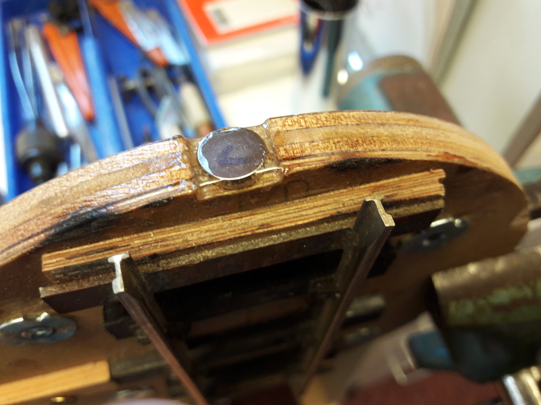
These are small three legged components that can sense magnetic pull. They are actually quite commonly used, such as counting teeth passing in a vehicle gearbox to calculate the road speed and distance. Again more research to establish a suitable model and five were soon on their way from China (I haven't destroyed any of them yet). One was setup on the breadboard with a recommended test program and hey presto, the LED lit up when the north face of a magnet was passed over it. The sensor was fitted onto some vero board and an 8mm dia neodymium magnet glued into a recess on the edge of the turntable disc.
|
|
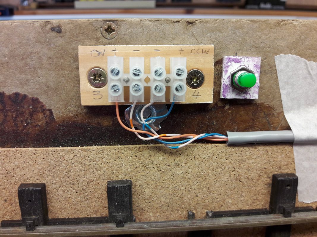
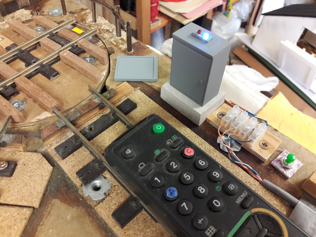
Redundant buttons 3 and 4 were reassigned to control the turntable direction. The infrared 'buttons' work like latched switches, so it's one press to switch on and another to switch off. When turning to the next track position two slow presses got the turntable going and it stopped when it reached the next track (controlled by the steps in the program). To go further than one track, the second press is given after the penultimate track is passed. In practice, it was sometimes difficult to remember if the second press had be made, which could be annoying.
|
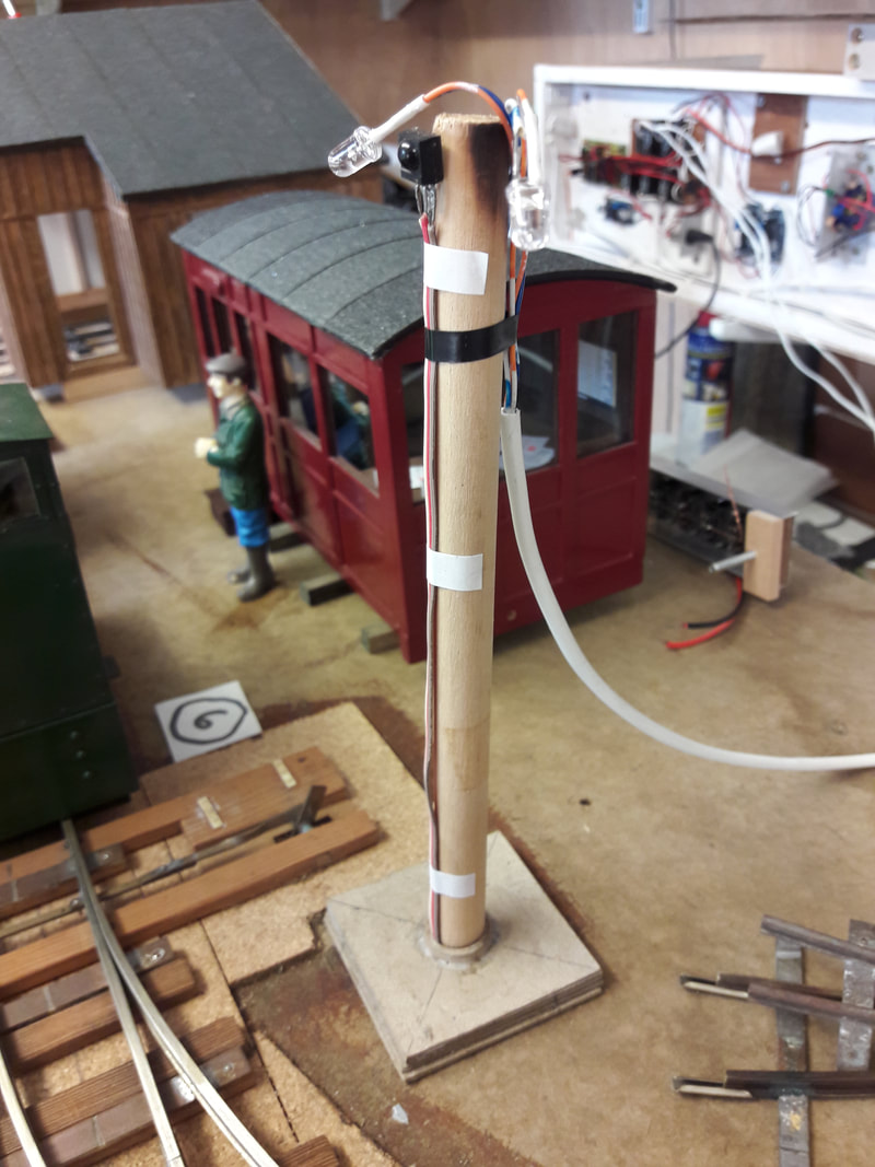
Two LED's were added to the relay circuits to indicate the button 'conditions', which worked well, but how to disguise them became an interesting question. At first, office lights were considered, one in each room. Although the rooms weren't detailed at this time, they probably would, so this didn't make long-term sense. Security lighting came next - the type with PIR sensors, which was much better. For the time being, the LED's have been placed at the top of the telegraph pole near the IR sensor. If no better idea is found, they will be made more like security-lights in due course.
|
|
Another modification to the main program added a sequence to align the turntable on start-up. This comprised an initial sweep to find the sensor, then (after some trial and error work) to move the correct number of steps to position 'zero' - the position from which all of the tracks have been programmed. It was a wonderful moment when it finally worked. A further modification was the addition of a momentary push button on the layout that forced a restart of the program just in case the table goes out of alignment.
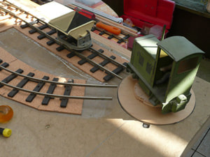
The rail alignment shown is not perfect at present as the TT baseboard needs realigning. Although usable, the tracks themselves could do with a bit of 'fettling' of the rail ends or at worst re-soldering the rails to resolve the matter. The key point is that the reason for abandoning the layout years ago has now been rectified and the layout can be progressed. |
|
|
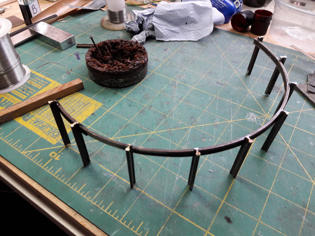
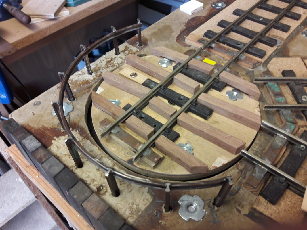
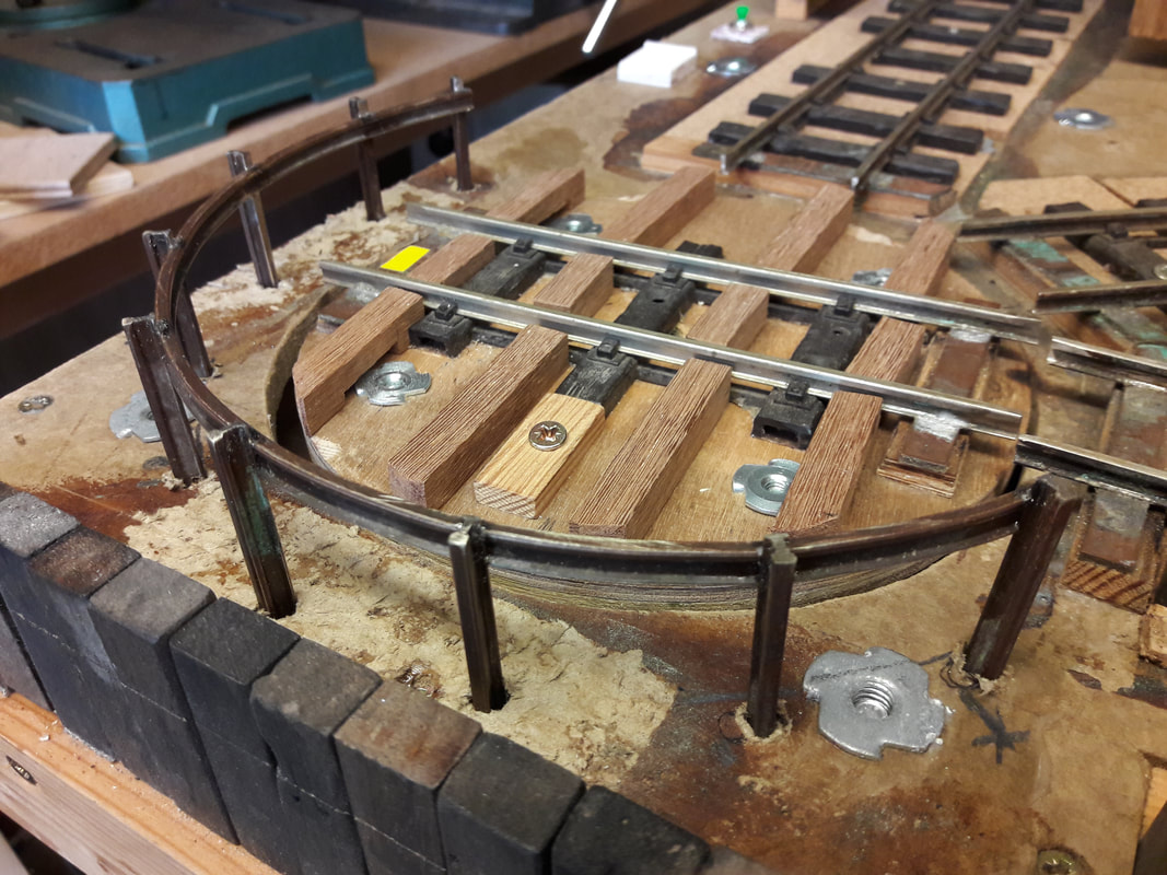
It had been a bit 'hairy' running a loco onto the turntable and then hoping you'd set the direction correctly to come off safely. I had previously bolted temporary wooden buffers on the ends of all roads, but the TT now needed a better solution. Old sections of track and points were cut up and shaped to form a circular barrier at buffer height. The barrier was filed to receive the uprights at intervals. Using a simple jig, the uprights were soldered in place, holes drilled in the baseboard and the barrier fitted. Even without gluing, it is robust enough for the most wayward operator.
|
Having built the barrier, I asked a friend about prototypical power for the turntable and was told that they would probably have been manually pushed around using a detachable lever which would not really be feasible with the new barrier in the way! The plan now is to have a posh electric/hydraulic drive system with an underground equipment pit (with chequer plate covers), a cabinet for electrical equipment along the fence and a separate box for controls in a safe location. More planning and more bits to make!
|
|
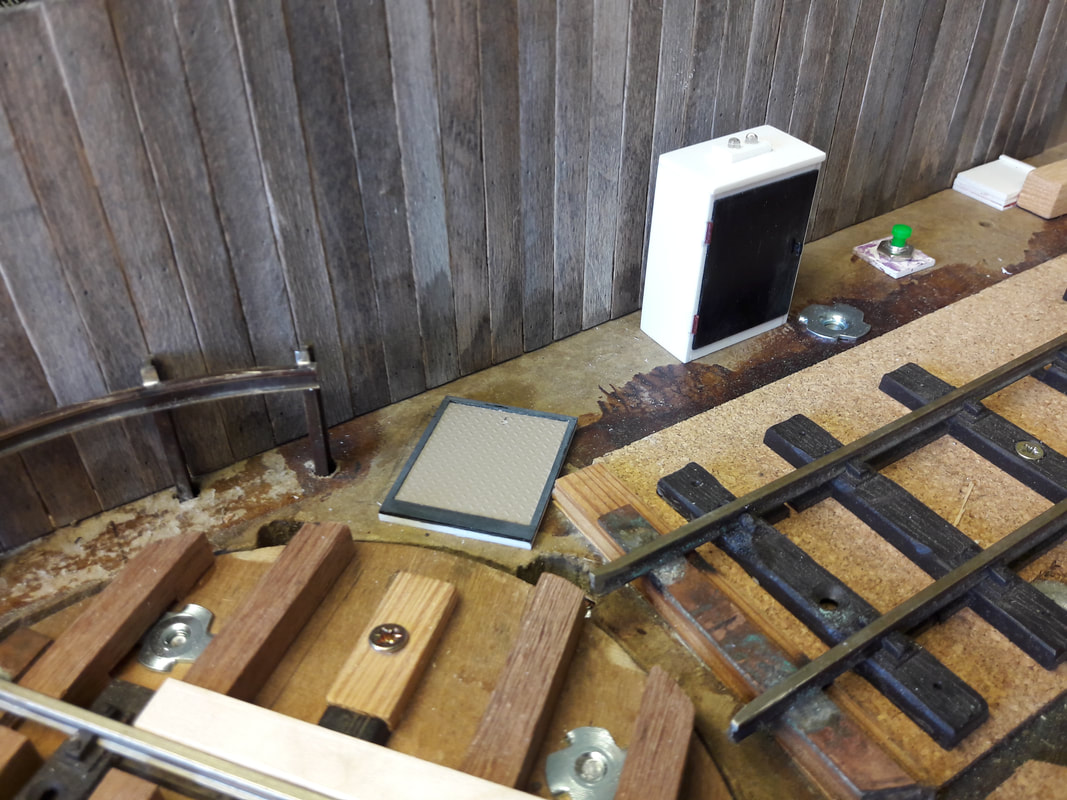
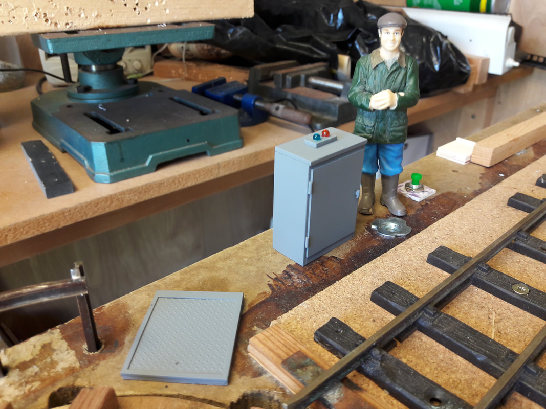
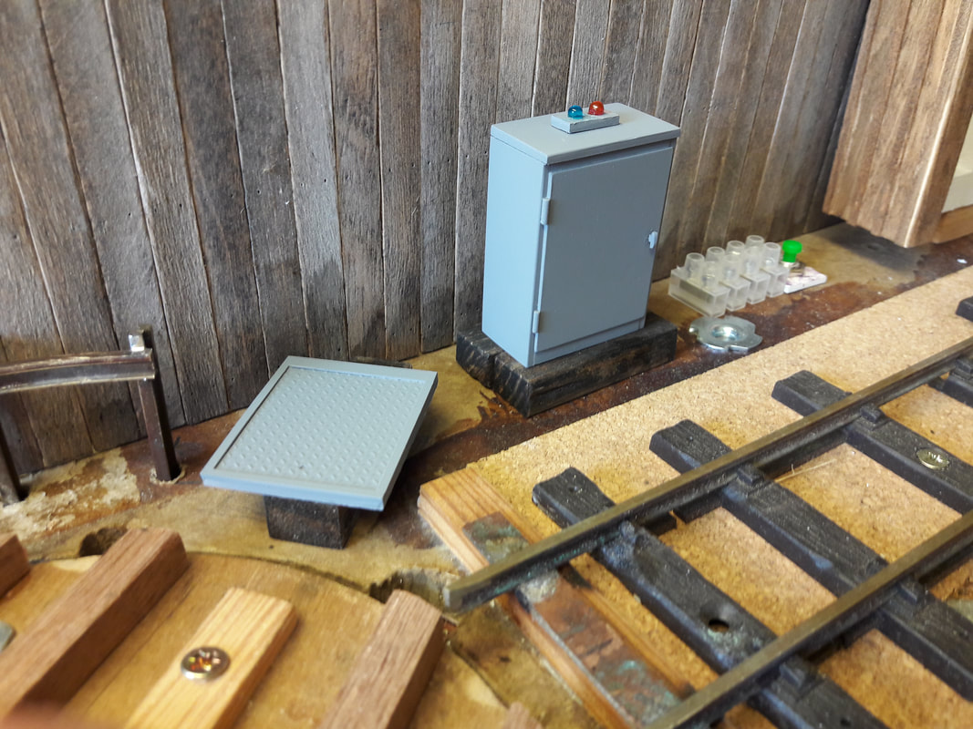
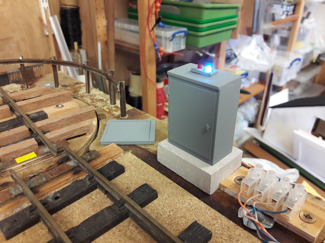
I Googled and found an external electrical cabinet, and made one from plasticard. Later, while watching a TV program about Lego Land I was intrigued at how they fixed a 'big ride' by getting into a floor access hatch to replace the gearbox - I had a prototype! A chequer-plate floor access panel and frame were fabricated. A smaller box was made to house the operating controls, mounted on the top of a pole.
|
It then occurred to me that the power cabinet could be the ideal location for some warning lights and so a pair of 3mm LED's were mounted in the top of the cabinet, one red and one blue. These replaced the turntable direction/stopping LED's on the telegraph pole. It's amazing how things fall into place sometimes.
|